BASIC ELECTRICAL MEASUREMENTS
Our basic electrical test instrument is the volt-ohm meter, or VOM. Various quantities can be measured by rotating the dial and placing the two probes in the appropriate locations.
Current: "I" is measured using an ammeter placed in series with the branch of the circuit you wish to test. Because we do not wish to modify the circuit by imposing an instrument of inappropriate characteristics, an ammeter is a very low-resistance device. If a significant potential difference exists between the input probes of an ammeter, the high current will at best blow a fuse and, at worse, destroy the instrument. ALWAYS place the ammeter in series with other circuit components.
Voltage: "V" is measured between two points - the voltmeter is placed in parallel with a circuit component. A voltmeter has a very high resistance so as to reduce any 'parallel-circuit' modification of the system (see Equation 5 and Problem 3). Among the specifications for voltmeters is 'input impedance', often expressed in ohms/volt. Modern electronic instruments often have input impedance of 100K or more ohms/volt.
Electrical resistance: (impedance) is measured by, first, shutting down any current in the circuit and, then, by placing the two probes of an ohmmeter on the two points between which electrical resistance is to be measured. This instrument allows a low, measured current to flow through the component and simultaneously measures the voltage drop, calculating and displaying the ratio (V/I), or R.
Limitations: an ohmmeter can not function properly if some unknown current also flows through the component. The circuit can not be active.
Resistance can also be measured if the current through a component is known and the voltage drop across the component measured. This requires simultaneous use of an ammeter with a voltmeter. Many sensitive resistance measurements use this method because it eliminates the effect of contact resistance - possibly large resistance exists where electrical current flows from one component into another. Charges carrying current are sometimes limited in their ability to move across such barriers.
Voltage is sometimes measured using a null indicator called a potentiometer. This device includes electrical networks involving a variable resistance that, when balance is achieved, allows no current to flow through the device. This means that potential difference can be measured without modifying the circuit (since no current flows through the device when it is balanced). Potentiometers are often able to measure voltages on the order of 1 millivolt or less under conditions where normal voltmeters are unsuitable. Potential difference is read directly from a calibrated dial attached to the variable resistance.
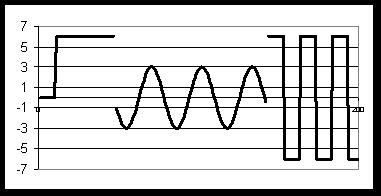
Alternating or direct current ? Batteries supply a steady DC voltage - voltage as a function of time is constant (at least until the battery begins to lose its power). Alternating current, the type of electrical energy obtained from household wall outlets, has voltage varying as a function of time in a sinusoidal manner, a sine wave that reverses direction 120 times/second (60 full cycles per second - a 60-hertz electrical signal). In order to measure AC current or voltage, the VOM must be set to the " ~ " setting. Some instruments use a square wave - a DC-type signal that changes polarity periodically. Figure 1 shows (a) a battery that provides 0 volts before the switch is thrown and 6 volts after; (b) an alternating current with peak voltage of 3 volts, and (c) a square wave that switches from +6 volts to -6 volts.

Figure 1: DC voltage
AC
voltage
Square
wave
The horizontal axis is the time axis.